
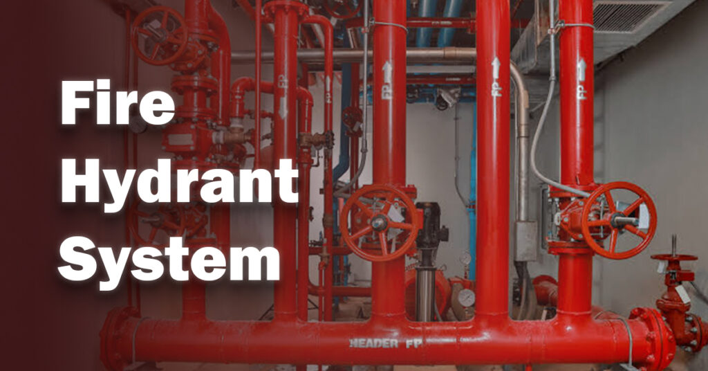
Fire can burn in minutes and damage the property and people to a great extent if treated in a timely manner. A fire hydrant system can be a valuable component to control fire in the event of an emergency and help firefighters to obtain a strong flow of water, thereby minimizing additional injury and property damage.
You will read here what a fire hydrant system is, how it functions, its principal components, its types and usage, and learn the importance of this system in fire safety.
What Is a Fire Hydrant System?
A fire hydrant system is an active fire protection infrastructure whose provision of water continuously during emergency fire suppression operations provides high flow. It joins the buried water mains or dedicated storage tanks to planned access points that enable firefighters to quickly attach high-pressure fire hoses.
All network outlets that can be accessed are classified as fire hydrants, so this is the most effective form of protection for large fires in the building structure and ensures that water is flowing through the piping distribution system at constant pressure.
Main Components of a Fire Hydrant System
The mechanisms of a fire hydrant are all interconnected mechanical components that put into play the overall workflow of the system.
- Water Reservoir and Pump Assembly: Suction tanks specifically designed with automatic electric main pumps, jockey pressure-maintenance pumps and a diesel backup engine.
- Underground Ring Main Piping: Massive steel or ductile iron feed pipes located under the site that transport compressed water.
- Operating Bonnet and Pentagonal Nut: The operating cap assembly with valve stem and a 5 piece operating nut, which is built for use with special wrenches.
- Valve stem and main valve seat: Internal mechanical shaft that operates a compression valve at the bottom of the mechanism.
- Hose Outlets and Fire Department Connections: Threaded discharge nozzles with protective caps supplied, outdoor fire truck pumper connections.
Read More: Fire Hose Cabinet | Types, Installation & Fire Safety Guide
How Does a Fire Hydrant Work?
The operation of a fire hydrant system is a result of the pressure-driven operation that begins with understanding. The line pressure decreases almost instantaneously when it is opened and firefighters attach fire hoses to it.
All water demands are immediately detected by the pressure sensors and activate the jockey pump. If there is a need for water then more water is required than the jockey pump can produce, the main electric or diesel fire pump will automatically kick on to ensure that this is maintained.
When the operating nut is turned counter-clockwise it feeds the internal stem in the opposite direction causing the main valve to be unseated and allowing pressurized water to surge through the barrel and into the connected hose lines at rates up to 1,500 gpm.
Wet vs Dry Fire Hydrants
| Operational Feature | Wet Fire Hydrant | Dry Barrel Hydrant |
|---|---|---|
| Water Location at Rest | Stored permanently inside the barrel up to each valve. | Held underground below the frost line. |
| Freeze Protection | None; suitable only for non-freezing regions. | Automatic drain valve empties barrel after use. |
| Primary Geographic Deployment | Warm climates such as Egypt and the Middle East. | Cold regions subject to freezing temperatures. |
Deploying a wet fire hydrant in mild and warm weather only makes sense because the water in the barrel will not freeze and will provide access to water on demand upon opening the valve.
On the other hand, in colder climates like in Europe, a dry fire hydrant is designed to allow all remaining water to flow out after the fire hydrant is closed, which does not cause barrel cracking due to ice expansion.
Read More: Fire Pump Testing | NFPA 25 Inspection Testing Guide
Fire Hydrant System Design
The engineering and design of a robust fire hydrant installation require specific hydraulic calculations to assure flow and residual pressure to satisfy local and international safety codes.
Closed loop ring mains are preferred by engineers as they have two water supplies, thus pressure loss is reduced when heavy demand occurs.
All the correct pipe sizing, placement of isolation valves and correct calculation of friction loss help provide the right amount of suppression power during critical emergencies.
Fire Hydrant Installation Requirements
- Open Clearance: The minimum distance around each unit should be kept clear to enable a quick sweep to attach the hose to a unit.
- Traffic Protection: Place breakaway couplings at ground level in areas near to driveways where vehicles might impact, preventing punctures to pipes and severing the coupling.
- Pushbacks: Use concrete thrust blocks or mechanical joint restraints at pipe elbows as a countermeasure for water hammer forces.
- Outlet Perforations: Keep depth and positioning to keep outlets facing primary roads for easy access with the nozzle at a “safe” height above grade to ensure full wrench swing.
NFPA Requirements
Installation & performance standards are detailed in NFPA 24 which sets hydrant spacing between 90 and 150 meters depending on the hazard risk. In the meantime, NFPA 1 specifies when units are within 120 meters from building entry points along hose pathways.
Further, NFPA 291 identifies a distinct color coding requirement for bonnets of hydrants for water flows of 20 psi residual pressure:
| NFPA 291 Flow Class | Bonnet / Cap Color | Available Flow Capacity (GPM) |
|---|---|---|
| Class AA | Light Blue | 1,500 GPM or higher |
| Class A | Green | 1,000 to 1,499 GPM |
| Class B | Orange | 500 to 999 GPM |
| Class C | Red | Less than 500 GPM |
The NFPA standards also define colors associated with bodies, such as yellow for municipal water, red for private facility systems and violet for non-potable water sources.
Read More: Fire Alarm System Design Requirements
Fire Hydrant Inspection & Maintenance
Inspection requirements outlined in NFPA 25 must be followed for sustained performance of a fire hydrant system. Routine fire hydrant maintenance avoids failures during emergencies, such as worn-out rubber seals or stem valve jamming.
Once a year visual inspections are recommended to ensure clear access, paint condition and integrity of the thread. Also, full flow tests and main flushes should be done every 5 years to check both the static and residual pressure as well as flush pipe sediment.
Common Fire Hydrant Problems
- Internal corrosion can cause the valve to become permanently closed and not allow any water to flow during a fire.
- If the tools used to remove the five-sided nut are not correct, that nut will not be able to be used with a standard wrench to open the valve.
- If the drain is obstructed in the dry models the water is prevented from draining out of the barrel and causes extensive frost damage in the water tank.
- High-pressure leakage can occur from damaged coupling threads due to exposure to the surrounding environment and poor fire hydrant maintenance.
Choosing the Right Hydrant System
Choosing a fire hydrant system that is best for your property requires balancing environmental conditions, building size, and regulatory codes. Wet barrel setups are useful for facilities that are located in warm climates such as Egypt, while facilities in cold climates will use dry barrel setups.
Working with the fire hydrant installation engineering experts guarantees that any new fire hydrant installation is fully compliant, economical, and ready upon completion.
Read More: Automatic Fire Sprinkler System | NFPA-Compliant Fire Protection
FAQs
How often should hydrants be tested?
The NFPA 25 guidelines say the visual checks should be done once a year, and the full flow testing should be performed at least every 5 years and the same period for line flushing.
What is the difference between wet and dry hydrants?
A wet fire hydrant in warm climates contains a pool of water in the barrel for rapid use, and in cold regions the dry fire hydrant drains the water out of the barrel after use so that it does not freeze on the inside.
What pressure is required for a fire hydrant?
A static conformance of 20 psi between the minimum and maximum required fire flow is often specified by standard fire protection codes for the discharge outlet.